Intel A300 Bedienungsanleitung
Stöbern Sie online oder laden Sie Bedienungsanleitung nach Motherboards Intel A300 herunter. Intel A300 User's Manual Benutzerhandbuch
- Seite / 192
- Inhaltsverzeichnis
- LESEZEICHEN
- Revision 2
- Copyright 3
- Packing List 4
- Table of Contents 5
- List of Figures 11
- List of Tables 13
- BIOS Menus 15
- Glossary 16
- 1 Introduction 17
- 1.1.1 A300 Applications 18
- 1.2 A300 Board Overview 20
- 1.2.1 A300 Connectors 21
- 2 Detailed Specifications 25
- 2.1 Overview 26
- 2.2 Dimensions 26
- 2.3 Data Flow 27
- 2.4 Compatible Processor 28
- 2.5 Intel 29
- 2.6 Intel 31
- 2.7 PCI Bus Components 34
- 2.8 LPC Bus Components 35
- 3 Unpacking 39
- 3.1 Anti-static Precautions 40
- 3.2 Unpacking 40
- 3.3 Unpacking Checklist 41
- 1 Mini jumper pack 42
- 1 Quick installation guide 42
- 1 Utility CD 42
- 4 Connector Pinouts 43
- 4.1.1 A300 Layout 44
- Connector Type Label 45
- PIN NO. DESCRIPTION 49
- 1 Speaker Out R 49
- 3 Speaker Out L 49
- 4.2.4 Fan Connectors 51
- Page 36 51
- 4.2.5 Front Panel Connector 52
- 4.2.7 IDE Connector 54
- Page 40 55
- 4.2.10 LED Connector 57
- Page 42 57
- 1 Power Button 59
- Page 46 61
- Page 48 63
- Page 50 65
- 1 GND 2 USBVCC4 66
- 3 GND 4 D4+ 66
- 5 D4 66
- 1 DTX2- 9 DTX1- 17 DTX0 68
- 2 DTX2+ 10 DTX1+ 18 DTX0+ 68
- 3 GND 11 GND 19 GND 68
- 4 N/C 12 N/C 20 N/C 68
- Page 54 69
- Figure 4-26: VGA Connector 74
- 5 Installation 75
- 5.1 Anti-static Precautions 76
- Read the user manual: 77
- 5.2.2 Installation Checklist 78
- WARNING: 82
- NOTE: 85
- Load Optimal Defaults 87
- Page 74 89
- Short 2-3 +5V LVDS 90
- LCD Rotate Description 91
- 1 LCD Rotate 91
- 2 GND 91
- 5.6 Chassis Installation 92
- Page 80 95
- 6 AMI BIOS 97
- Primary IDE Master 98
- Primary IDE Slave 98
- Secondary IDE Master 98
- Secondary IDE Slave 98
- 6.2 PCI/PnP 120
- 6.3 Boot 125
- BIOS Menu 11: Boot 126
- CD/DVD 130
- A300 Motherboard 132
- Page 117 132
- 6.4 Security 133
- Page 119 134
- 6.5 Chipset 135
- DRAM CAS# Latency [2.5] 137
- DRAM Burst Length [8] 137
- Internal VGA 138
- PCI/Int-VGA 138
- 6.6 Power 141
- 6.7 Exit 144
- Page 130 145
- Page 131 146
- Page 132 147
- 7 Software Drivers 148
- Page 134 149
- Page 135 150
- Page 136 151
- Page 137 152
- Page 138 153
- Page 139 154
- Page 140 155
- Page 141 156
- Page 142 157
- Page 143 158
- Page 144 159
- CAUTION! 160
- Page 145 160
- Page 146 161
- Page 147 162
- Page 148 163
- A BIOS Options 164
- Page 154 169
- B GPIO Connection 170
- Bit 4 00h 00h 172
- Bit 5 00h 00h 172
- Bit 6 00h 00h 172
- Bit 7 00h 00h 172
- Page 158 173
- C Watchdog Timer 174
- Page 162 177
- D Address Mapping 178
- D.1 Address Map 179
- D.3 IRQ Mapping Table 180
- D.4 DMA Channel Assignments 180
- Page 166 181
- E External AC’97 Audio 182
- E.1 Introduction 183
- Page 170 185
- F Index 188
- Page 174 189
Inhaltsverzeichnis
A300 Motherboard A300 Motherboard Page i
A300 MotherboardE.2.2 Sound Effect Manager Configuration Options... 170 F INDEX...
A300 Motherboard method of addressing data on a disk drive is supported or not. Block Mode: Block mode boosts IDE drive performance by increasin
A300 Motherboard LS-120 LBA/Large Mode [Auto] The LBA/Large Mode BIOS option disables or auto detects LBA (Logical Block Addressing). LBA is a
A300 Motherboard this value if the IDE disk drive support cannot be determined. 0 PIO mode 0 selected with a maximum transfer rate of 3.3MBps 1
A300 Motherboard 32Bit Data Transfer [Disabled] The 32Bit Data Transfer BIOS option enables or disables 32-bit data transfers. Disabled Preve
A300 Motherboard Auto (Default) This selection enables the BIOS to auto detect the IDE disk drive type attached to the specified channel. This set
A300 Motherboardmanufactured after 1999. For other disk drives, such as IDE CD-ROM drives, check the specifications of the drive.) DMA Mode [Auto]
A300 Motherboard 6.1.2 Super IO Configuration The Super IO Configuration menu (BIOS Menu 3) sets or changes the configurations for the serial ports.
A300 Motherboardaddress is IRQ3 Serial Port2 Address [2F8/IRQ3] The Serial Port2 Address option allows BIOS to select the Serial Port 2 base addre
A300 Motherboard This option allows BIOS to select the base addresses for serial port 4. Disabled No base address is assigned to serial port 4
A300 Motherboard 11 (Default) Serial port 5 IRQ address is 11 Serial Port6 Address [2E0] This option allows BIOS to select the base addresses fo
A300 Motherboard List of Figures Figure 1-1: A300 Overview ...
A300 Motherboard BIOS Menu 4: Hardware Health Configuration FAN 1 Mode Setting: [Full On] The FAN 1 Mode Setting has the following options: Fu
A300 Motherboard Slop PWM 1: 0 PWM , 2 PWM (Default), 4 PWM or 8 PWM, 16 PWM, 32 PWM, 64 PWM FAN 2 Mode Setting: [Full On] The FAN 2 Mode Sett
A300 Motherboard The ACPI Configuration menu (BIOS Menu 5) configures the Advanced Configuration and Power Interface (ACPI) and Power Management (APM
A300 Motherboard BIOS Menu 6: Advanced ACPI Configuration ACPI APIC Support [Enabled] Use the ACPI APIC Support option to add a pointer to an ACPI
A300 Motherboard Use APIC ACPI SCI IRQ option to enable the system to send a flag report to the ACPI OS if a SCI IRQ interrupt event is made via the
A300 MotherboardBIOS Menu 7: MPS Configuration MPS Revision [1.4] The Multiprocessor Specification (MPS) for OS specifies the MPS version to be us
A300 Motherboard BIOS Menu 8: USB Configuration USB Configuration The USB Configuration field shows the system USB configuration. The items listed
A300 Motherboard Legacy USB Support [Enabled] The Legacy USB Support BIOS option refers to USB mouse and USB keyboard support. Normally if this op
A300 Motherboard 6.1.6.1 USB Mass Storage Device Configuration Use the USB Mass Storage Device Configuration menu (BIOS Menu 9) to configure USB mass
A300 Motherboard 40 Sec POST waits 40 seconds for the USB mass storage device after the start unit command. Device ## The Device## field lists
A300 MotherboardFigure 4-23: J7 Connector...55 Figure 4-24: PS
A300 Motherboard floppy image. This option works only for drives formatted with FAT12, FAT16 or FAT32. Hard Disk Allows the USB device to be emul
A300 MotherboardBIOS Menu 10: PCI/PnP Configuration Plug & Play O/S [No] Use the Plug & Play O/S BIOS option to specify whether system plu
A300 Motherboard Use the PCI Latency Timer option to specify the PCI latency time. The latency time is measured in units of PCI clock cycles for the
A300 MotherboardThe graphics chipset can be mounted on a PCI card. Always check with the adapter card manual first, before modifying the default sett
A300 Motherboard adapter card is installed in PCI Slot 4. PCI Slot 5 PCI Slot 5 is selected as the location of the OffBoard PCI IDE adapter card.
A300 MotherboardUse the DMA Channel# option to assign a specific DMA channel to a particular PCI/PnP device. Available DEFAULT The specified DMA is
A300 Motherboard BIOS Menu 11: Boot 6.3.1 Boot Settings Configuration The Boot Settings Configuration menu (BIOS Menu 12) configures advanced system
A300 Motherboard BIOS Menu 12: Boot Settings Configuration Quick Boot [Enabled] The Quick Boot BIOS option makes the computer speed up the boot pr
A300 Motherboard Enabled (Default) Can be booted from a remote system through the LAN Quiet Boot [Disabled] The Quiet Boot BIOS option allows t
A300 Motherboardautomatically when the computer system boots up. This allows the immediate use of the 10-key numeric keypad located on the right side
A300 Motherboard List of Tables Table 1-1: Technical Specifications ...9 Tab
A300 Motherboard settings. Hit ‘DEL’ Message Display [Enabled] The Hit “DEL” Message Display option allows specifies whether the instruction to hi
A300 MotherboardBIOS Menu 13: Boot Device Priority Settings 6.3.3 Removable Drives The Removable Drives menu (BIOS Menu 14) specifies the boot sequen
A300 Motherboard BIOS Menu 14: Removable Drives Page 117
A300 Motherboard6.3.4 CD/DVD Drives The CD/DVD Drives menu is similar to the Removable Drives BIOS Menu 14 and it specifies the boot sequence of the
A300 Motherboard BIOS Menu 15: Security Change Supervisor Password The default setting for the Change Supervisor Password is Not Installed. If a s
A300 Motherboard6.5 Chipset The Chipset menu (BIOS Menu 16) has two sub-menus, NorthBridge Configuration and SouthBridge Configuration. The NorthBrid
A300 Motherboard The NorthBridge Configuration menu (BIOS Menu 17) allows the northbridge chipset to be configured. BIOS Menu 17: NorthBridge Chipset
A300 MotherboardThe Configure DRAM Timing by SPD option determines if the system uses the SPD (Serial Presence Detect) EEPROM to configure the DRAM t
A300 Motherboard The Init. Graphic Adapter Priority option selects the graphics controller the system uses as a primary boot device. The options are:
A300 Motherboard CRT EFP LFP CRT + EFP CRT + LFP (Default) Flat Panel Type [1280x1024 48bits ] The Flat Panel Type BIOS option spec
A300 MotherboardTable 4-23: RJ-45 Ethernet Connector Pinouts...55 Table 4-24: RJ-45 Ethernet Con
A300 Motherboard BIOS Menu 18: SouthBridge Chipset Configuration OnBoard AC’97 Audio [Auto] The OnBoard AC’97 Audio option enables or disables th
A300 MotherboardThe OnBoard LAN1 option enables or disables the on-board LAN1. Disabled On-board LAN1 device manually disabled Enabled (Defaul
A300 Motherboard BIOS Menu 19: Power Power Management/APM [Enabled] The Power Management/APM BIOS option allows access to the advanced power man
A300 Motherboardturned on or off Suspend When the power button is pressed the system goes into suspend mode Restore on AC Power Loss [Last Sta
A300 Motherboard on-board LAN controller activity Resume On RTC Alarm [Disabled] The Resume On RTC Alarm determines when the computer is roused fr
A300 Motherboard BIOS Menu 20: Exit Save Changes and Exit If configuration changes are complete, select this option to save them and exit the
A300 Motherboard This option loads optimal default values for each of the parameters on the Setup menus. F9 key can be used for this operation. Lo
A300 MotherboardTHIS PAGE IS INTENTIONALLY LEFT BLANK Page 132
A300 Motherboard Chapter 7 Software Drivers 7 Page 133
A300 Motherboard7.1 Available Software Drivers NOTE: The contents of the CD may vary throughout the life cycle of the product and is subject to chan
A300 Motherboard BIOS Menus BIOS Menu 1: IDE Master Configuration...84 BIOS Menu 2: I
A300 Motherboard Figure 7-1: InstallShield Wizard Preparation Screen Step 1: The “Welcome” window in Figure 7-2 appears next. Figure 7-2: Welcome
A300 Motherboard Figure 7-3: License Agreement Step 3: Agree to the license terms by clicking “Yes”. The “Readme” in Figure 7-4 appears. Page 136
A300 Motherboard Figure 7-4: Readme Information Step 4: Click “Yes”. The driver is installed on the computer. After the installation is complete, t
A300 Motherboard Figure 7-5: Restart the Computer 7.3 RealTek Audio Driver Installation To install the RealTek AC’97 Audio driver, please follow the
A300 Motherboard Figure 7-6: Audio Driver Install Shield Wizard Starting Step 3: The RealTek Audio Setup prepares the install shield to guide throu
A300 Motherboard Figure 7-7: Audio Driver Welcome Screen Figure 7-8: Audio Driver Software Configuration Step 5: At this stage the “Hardware Instal
A300 Motherboard To continue the installation process, click the “Continue Anyway” button. Figure 7-9: Audio Driver Digital Signal Step 6: After th
A300 Motherboard Figure 7-10: Audio Driver Installation Complete Step 7: The confirmation screen shown in Figure 7-10 allows user to restart the com
A300 Motherboard Figure 7-11: VGA Driver Installation InstallShield Wizard Screen Step 3: To continue installing click “Next” and a welcome screen
A300 Motherboard Figure 7-12: VGA Driver Welcome Screen Step 4: To continue installing click “Next”. After the driver installation process is comple
A300 MotherboardGlossary AC ’97 Audio Codec 97 ACPI Advanced Configuration and Power Interface APM Advanced Power Management ARMD ATAPI Removable
A300 Motherboard Figure 7-13: GMA Driver Installation Complete Step 5: The confirmation screen shown in Figure 7-13 allows user to restart the comp
A300 Motherboarddrives whether configuring the SATA disk drives into RAID volumes or using them as individual disk drives. The system BIOS can identi
A300 Motherboard SATA/RAID Controller for Windows XP and press ENTER to continue. Step 9: The follow-up window lists out the devices to be installed
A300 MotherboardStep 8: Repeat step 1, but select ALi ATA/RAID Controller at step 4. Page 148
A300 Motherboard A BIOS Options Appendix A Page 149
A300 Motherboard IDE Master and IDE Slave ...83 Auto-Detected
A300 Motherboard Slop PWM 1 ...96 FAN 2 Mode S
A300 Motherboard Quiet Boot [Disabled] ... 113 AddOn ROM D
A300 Motherboard Discard Changes and Exit ... 130 Discard Changes
A300 MotherboardTHIS PAGE IS INTENTIONALLY LEFT BLANK Page 154
A300 Motherboard 1 Introduction Chapter 1 Page 2
A300 Motherboard B GPIO Connection Appendix B Page 155
A300 MotherboardB.1 GPIO Settings and Default Values B.1.1 GPIO Settings Two addresses (320h and 321h) on the LVC chipset are reserved to control the
A300 Motherboard Bit 4 00h 00h Bit 5 00h 00h Bit 6 00h 00h Bit 7 00h 00h B.2 Assembly Language Samples B.2.1 GPIO Initialization Procedure Th
A300 MotherboardMOV DX, 320h Moves 320h into the DX data register for one of the GPIO pins MOV AL, ZZh Moves the user defined output data ZZh into th
A300 Motherboard C Watchdog Timer Appendix C Page 159
A300 Motherboard NOTE: The following discussion applies to DOS environment. IEI support is contacted or the IEI website visited for specific drive
A300 Motherboard NOTE: When exiting a program it is necessary to disable the Watchdog Timer, otherwise the system resets. Example program: ; INIT
A300 MotherboardTHIS PAGE IS INTENTIONALLY LEFT BLANK Page 162
A300 Motherboard D Address Mapping Appendix D Page 163
A300 MotherboardD.1 Address Map I/O address Range Description 000-01F DMA Controller 020-021 Interrupt Controller 040-043 System time 060-06F Keyboar
A300 Motherboard 1.1 A300 Overview The A300 is a multimedia Pentium® Mobile processor-based motherboard that powers a Point-of-Care terminal or panel
A300 Motherboard D.3 IRQ Mapping Table IRQ0 System Timer IRQ8 RTC clock IRQ1 Keyboard IRQ9 ACPI IRQ2 Available IRQ10 COM4/COM6 IRQ3 COM2 IRQ11 CO
A300 MotherboardTHIS PAGE IS INTENTIONALLY LEFT BLANK Page 166
A300 Motherboard E External AC’97 Audio CODEC Appendix E Page 167
A300 MotherboardE.1 Introduction The motherboard comes with an on-board Realtek ALC203 CODEC. Realtek ALC203 is a 16-bit, full duplex AC’97 Rev. 2.3
A300 Motherboard To access the Sound Effects Manager, please do the following: Step 9: Install the audio CODEC driver. Step 10: Click either: T
A300 Motherboard Note: The Sound Effect Manager shown above is for the RealTek ALC655 audio CODEC. Different CODECs may have different sound manager
A300 Motherboard NOTE: Not all RealTek Sound Effect Managers have all the above listed options. The Sound Effect Manager loaded onto the system may
A300 Motherboard Connector Sensing:- Realtek ALC655 detects if an audio device is plugged into the wrong connector. If an incorrect device is plugg
A300 Motherboard F Index Page 173
A300 Motherboard A ACPI 97, 98 airflow 77 anti-static precautions 25, 61 anti-static pad 25, 61 anti-static wristband 25, 61 handling 25, 61 self-
A300 Motherboard1.1.2 A300 Benefits Some of the A300 benefits include: Clinical Information System (CIS) integration Filmless solution by PACS
A300 MotherboardIrDA 42 LED 43 power button 44 RS-232 46 RS-422/485 45 system panel 47 TFT LCD LVDS (20-pin) 48 USB (5-pin) 51 USB (8-pin) 50 co
A300 Motherboard clear CMOS 72 COM port setting 73 jumper configuration 71 jumper settings 70 LCD rotation 76 LCD voltage selection 75 K Keyboa
A300 MotherboardS Serial port 7, 92, 93, 94 serial port connector 57 location and pinouts 57 serial port devices 80 socket 479 CPU cooling kit 6
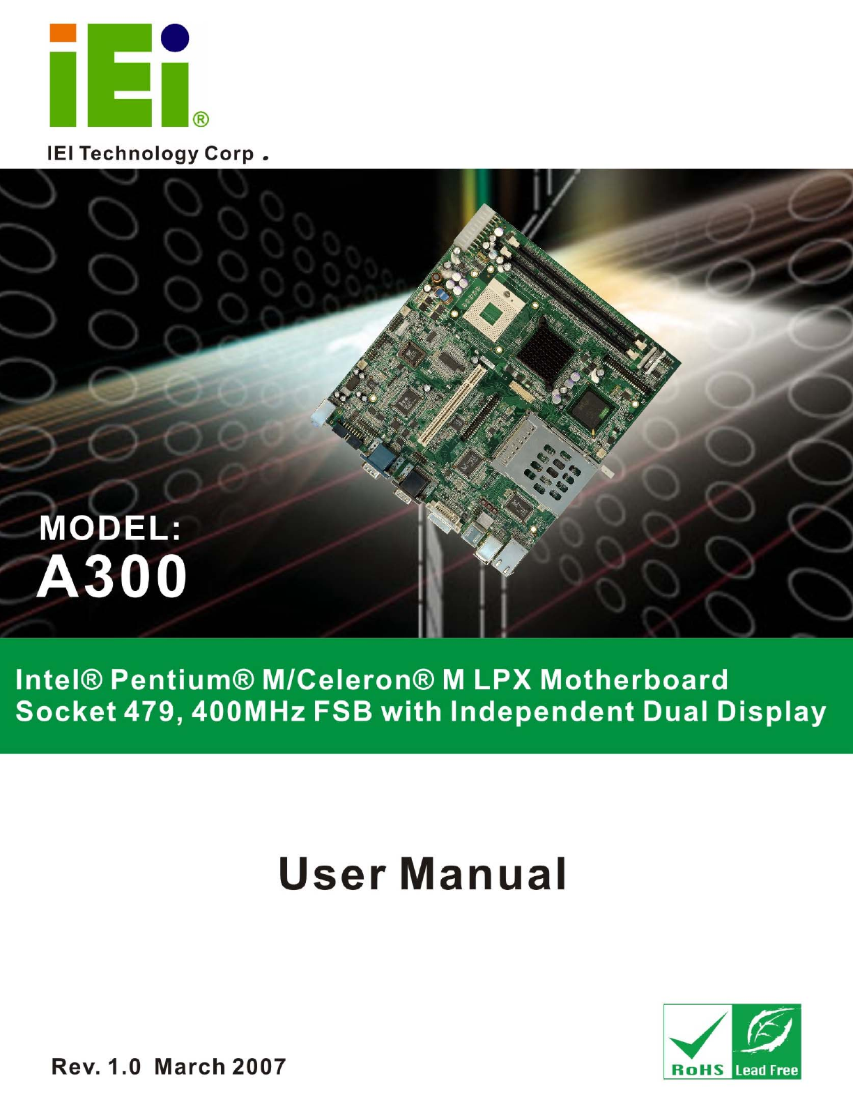
A300 MotherboardRevision MODEL A300 Intel® Pentium® M/Celeron® M Motherboard Revision Number Description Date of Issue 1.0 Initial release Mar
A300 Motherboard 1.2 A300 Board Overview Figure 1-1: A300 Overview Page 5
A300 MotherboardFigure 1-2: A300 Solder Side Overview 1.2.1 A300 Connectors The A300 has the following connectors on-board: 1 x ATX power connecto
A300 Motherboard 1 x Disk LED connector 1 x PCMCIA slot 1 x Power button connector 3 x RS-232 serial port connectors 1 x RS-422/485 se
A300 MotherboardSpecification A300 CPU Intel® Pentium M/Celeron M 400Mhz FSB up to 2.10GHz System Chipset Intel® 855GME + ICH4 Display CRT integrate
A300 Motherboard Dimensions 235mm x 220mm Weight (GW/NW) 1200g/680g Table 1-1: Technical Specifications Page 9
A300 Motherboard 2 Detailed Specifications Chapter 2 Page 10
A300 Motherboard 2.1 Overview This chapter describes the specifications and on-board features of the A300 in detail. 2.2 Dimensions 2.2.1 Board Dimen
A300 Motherboard2.2.2 External Interface Panel Dimensions External peripheral interface connector panel dimensions are shown in Figure 2-2. Figure 2
A300 Motherboard 2.4 Compatible Processor 2.4.1 CPU Overview Socket 479 Intel® Pentium® M processors with enhanced Intel SpeedStep® Technology and So
A300 Motherboard2.5 Intel® 855GME Chipset Graphics Memory Controller Hub 2.5.1 Intel® 855GME Overview The Intel® 855GME chipset comes with the foll
A300 Motherboard Copyright COPYRIGHT NOTICE The information in this document is subject to change without prior notice in order to improve reliabilit
A300 Motherboard Graphics Core Frequency o Display/Render frequency up to 250 MHz (with 1.35 V core voltage) 3D Graphics Engine o 3D Setup and
A300 Motherboard Enhanced Hardware Binning Instruction Set supported Bi-Cubic Filtering supported Linear Gamma Blending for Video Mixer Rende
A300 Motherboard Alert On LAN* (AOL) and Alert On LAN 2* (AOL2) 2.6.2 Intel® ICH4 IDE Interface The single A300 IDE connector supports two IDE har
A300 Motherboardaudio connector. The audio connector is connected to an audio kit with an embedded AC’97 audio codec. The AC’97 controller supports u
A300 Motherboard BIOS chipset Super I/O chipset 2.6.8 BIOS The BIOS flash memory chip on the A300 has a licensed copy of AMI BIOS loaded onto i
A300 Motherboard Crossover Detection & Auto-Correction Wake-on-LAN and remote wake-up support Microsoft® NDIS5 Checksum Offload (IP,
A300 Motherboard PXE (Pre-boot Execution Environment) support USB booting support 2.8.3 Super I/O Chipset The iTE IT8712F Super I/O chipset is
A300 Motherboard2.8.3.2 Super I/O Enhanced Hardware Monitor The Super I/O Enhanced Hardware Monitor monitors three thermal inputs, VBAT internally, a
A300 Motherboard Eight voltage inputs on the A-300 Super I/O Enhanced Hardware Monitor monitor the following voltages: Vcore +3.30Vin +5.00V
A300 Motherboard 3 Unpacking Chapter 3 Page 24
A300 MotherboardPacking List NOTE: If any of the components listed in the checklist below are missing, please do not proceed with the installation.
A300 Motherboard 3.1 Anti-static Precautions WARNING: Failure to take ESD precautions during the installation of the A300 may result in permanent da
A300 Motherboard3.3 Unpacking Checklist NOTE: If some of the components listed in the checklist below are missing, please do not proceed with the in
A300 Motherboard 1 Mini jumper pack 1 Quick installation guide 1 Utility CD Table 3-1: Package List Contents Page 27
A300 Motherboard 4 Connector Pinouts Chapter 4 Page 28
A300 Motherboard 4.1 Peripheral Interface Connectors Section 4.1.2 shows peripheral interface connector locations. Section 4.1.2 lists all the periph
A300 Motherboard Figure 4-2: Connector and Jumper Locations (Solder Side) 4.1.2 Peripheral Interface Connectors Table 4-1 shows a list of the periph
A300 Motherboard Audio connector 3-pin wafer connector AUDIO1 Compact Flash (CF) connector 50-pin CF slot CN7 Fan connector (CPU) 3-pin wafer co
A300 Motherboard4.1.3 External Interface Panel Connectors Table 4-2 lists the rear panel connectors on the A300. Detailed descriptions of these conne
A300 Motherboard The 20-pin ATX power connector is connected to an AT power supply. Figure 4-3: ATX Power Connector Location PIN NO. DESCRIPTION
A300 MotherboardCN Pinouts: See Table 4-4The 3-pin audio connector is connected to speakers the output of audio signals from the system. Figure 4-4
A300 Motherboard Table of Contents 1 INTRODUCTION...
A300 Motherboard A CF Type I or Type II memory card is inserted to the CF socket on the solder side of the A300. Figure 4-5: CF Card Socket Locat
A300 Motherboard17 N/C 42 IORDY 18 SA2 43 SDREQ 19 SA1 44 SDACK# 20 SA0 45 HDD_ACTIVE# 21 DATA 0 46 66DET 22 DATA 1 47 DATA 8 23 DATA 2 48 DAT
A300 Motherboard PIN NO. DESCRIPTION 1 Fan Speed Detect 2 +12V 3 GND Table 4-6: System Fan Connector Pinouts4.2.5 Front Panel Connector CN Label: C
A300 MotherboardPIN DESCRIPTION PIN DESCRIPTION 1 Speaker Up 2 LCD On/Off 3 Speaker Down 4 5V Power 5 GND 6 Power Button 7 BKLT Up 8 Standby Powe
A300 Motherboard PIN NO. DESCRIPTION PIN NO. DESCRIPTION 1 GND 2 VCC5 3 GPIO0 4 GPIO1 5 GPIO2 6 GPIO3 7 GPIO4 8 GPIO5 9 GPIO6 10 GPIO7 Table
A300 MotherboardPIN NO. DESCRIPTION PIN NO. DESCRIPTION 1 RESET# 2 GROUND 3 DATA 7 4 DATA 8 5 DATA 6 6 DATA 9 7 DATA 5 8 DATA 10 9 DATA
A300 Motherboard The inverter connector is connected to the LCD backlight. Figure 4-10: Inverter Connector Location PIN NO. DESCRIPTION PIN NO. DE
A300 Motherboard Figure 4-11: IR Connector Location PIN NO. DESCRIPTION 1 VCC5 2 NC 3 IRRX 4 GND 5 IRTX Table 4-11: IR Connector Pinouts4.2.10 LED
A300 Motherboard Figure 4-12: LED Connector Locations PIN NO. DESCRIPTION 1 +LED 2 -LED Table 4-12: LED Connector Pinouts 4.2.11 Power Button Conn
A300 Motherboard Figure 4-13: Power Button Connector Location PIN NO. DESCRIPTION 1 Power Button 2 GND Table 4-13: Power Button Connector Pinouts
A300 Motherboard2.6.8 BIOS... 19 2.7 PC
A300 Motherboard Figure 4-14: Serial Port Connector Location PIN NO. DESCRIPTION PIN NO. DESCRIPTION 1 DCD3 2 DSR3 3 RX3 4 RTS3 5 TX3 6 CTS
A300 MotherboardThe serial ports connectors connect to RS-232 serial port device. Figure 4-15: RS-232 Serial Port Connector Locations PIN NO. DESC
A300 Motherboard PIN NO. DESCRIPTION PIN NO.DESCRIPTION 1 DCD6 2 DSR6 3 RX6 4 RTS6 5 TX6 6 CTS6 7 DTR6 8 RI6 9 GND 10 GND Table 4-17: COM6 Seri
A300 Motherboard Figure 4-16: Front Panel Connector Location PIN DESCRIPTION PIN DESCRIPTION 1-3 POWER LED 2-8 SPEAKER 5-7 PWR BUTTON 10-12 RESET
A300 Motherboard Figure 4-17: TFT LCD LVDS Connector Pinout Locations PIN NO. DESCRIPTION PIN NO. DESCRIPTION1 GND 2 GND 3 Rin0+ 4 Rin0- 5 Ri
A300 Motherboard4.2.16 Internal USB Connectors (8-Pin) CN Label: USB2 CN Type: 8-pin header (2x4) CN Location: See Figure 4-18CN Pinouts: See Ta
A300 Motherboard 4.2.17 Internal USB Connectors (5-Pin) CN Label: USB3 and USB4 CN Type: 5-pin wafer connector (1x5) CN Location: See Figure 4-19
A300 Motherboard4.3 External Peripheral Interface Connectors 4.3.1 External Peripheral Interface Connector Overview The A300 external peripheral inte
A300 Motherboard Microphone (Pink): Connects a microphone. Figure 4-21: Audio Connector 4.3.3 DVI-I Connector CN Label: DVI1 CN Type: DVI inter
A300 Motherboard5 N/C 13 N/C 21 N/C 6 SB_CK_C 14 PVDD1 22 GND 6 SB_DA_C 15 GND 23 DTXC+ 8 V_SYNC 16 GND 24 DTXC- C1 R C3 B 25 GND C5 GND C6
A300 Motherboard 4.2.4 Fan Connectors... 36 4.2.5 Front
A300 Motherboard A13 ACT B13 ACT A14 LINK B14 LINK A15-17 GND B15-17 GND Table 4-23: RJ-45 Ethernet Connector Pinouts Figure 4-23: J7 Connector
A300 Motherboard Figure 4-24: PS/2 Pinouts PIN NO. DESCRIPTION PIN NO. DESCRIPTION 1 KB DATA 7 MS DATA 2 NC 8 NC 3 GND 9 GND 4 5V 10 5V 5 KB CL
A300 Motherboard 5 TX1 6 CTS1 7 DTR1 8 RI1 9 GND 10 GND Table 4-26: RS-232 Serial Port (COM 1) Pinouts Figure 4-25: Serial Port Pinout Locations
A300 Motherboard4.3.8 USB Combo Ports CN Label: USB1 CN Type: USB Combo port CN Location: See Figure 4-20CN Pinouts: See Table 4-28The two USB com
A300 Motherboard 4 NC 12 DDCDAT 5 GROUND 13 HSYNC 6 GROUND 14 VSYNC 7 GROUND 15 DDCCLK 8 GROUND Table 4-29: VGA Connector Pinouts Figure 4-
A300 Motherboard 5 Installation Chapter 5 Page 60
A300 Motherboard 5.1 Anti-static Precautions WARNING: Failure to take ESD precautions during the installation of the A300 may result in permanent da
A300 Motherboard5.2 Installation Considerations NOTE: The following installation notices and installation considerations should be read and underst
A300 Motherboard o When working with the A300, make sure that it is disconnected from all power supplies and that no electricity is being fed into th
A300 Motherboard5.3 CPU and CPU Cooling Kit Installation WARNING: A CPU should never be turned on without the specified cooling kit being installed.
A300 Motherboard5.4.2 CF Card Installation... 69 5.5 JUMPER SETT
A300 Motherboard Step 1: Unlock the CPU retention screw. When shipped, the retention screw of the CPU socket should be in the unlocked position. If
A300 MotherboardSee Figure 5-2.Step 0: Figure 5-2: Lock the CPU Socket Retention Screw 5.3.2 Cooling Kit CF-479B-RS Installation Figure 5-3: IEI
A300 Motherboard WARNING: Do not wipe off (accidentally or otherwise) the pre-sprayed layer of thermal paste on the bottom of the CF-479A-RS/CF-518-
A300 MotherboardStep 5: Connect the fan cable. Connect the cooling kit fan cable to the fan connector on the motherboard. Carefully route the cable
A300 Motherboard Figure 5-6: Installing the DIMM Module Step 2: Slowly slide the DIMM module along the plastic guides on both ends of the socket. P
A300 Motherboardsocket. Step 3: Insert the CF card. Gently insert the CF card into the socket making sure the socket pins are properly inserted int
A300 Motherboard Before the A300 is installed in the system, the jumpers must be set in accordance with the desired configuration. The jumpers on the
A300 Motherboard Figure 5-8: CF Card Setup Jumper Location 5.5.2 Clear CMOS Jumper Jumper Label: JP2 Jumper Type: 3-pin header Jumper Settings: See
A300 Motherboard After having done one of the above, save the changes and exit the CMOS Setup menu. The clear CMOS jumper settings are shown in Tab
A300 MotherboardThe COM Port Setting jumper configures pin 9 on COM 1, COM 3 or COM 2 as either a +5V, +12V power source. The CN13 jumper also sets t
A300 Motherboard 6.6 POWER ... 126 6.
A300 Motherboard Figure 5-10: COM Port Setting Jumper Location 5.5.4 LCD Voltage Selection WARNING: Permanent damage to the screen and A300 may occ
A300 Motherboard Figure 5-11: LCD Voltage Selection Jumper Location 5.5.5 LCD Rotation Jumper Jumper Label: CN16 Jumper Type: 2-pin header Jumper Se
A300 Motherboard The LCD Rotate jumper location is shown in Figure 5-12. Figure 5-12: LCD Rotate Jumper Location 5.6 Chassis Installation 5.6.1 Airf
A300 Motherboardthe cooling fan of a power supply can also help generate airflow through the board surface. 5.6.2 Motherboard Installation To instal
A300 Motherboard Figure 5-13: IDE Cable Connection Step 3: Connect the cable to an IDE device. Connect the two connectors on the other side of the
A300 Motherboardthe A300 keyboard/mouse connector. See Figure 5-14. Step 3: Insert the cable connectors. Once the cable connector is properly aligne
A300 Motherboard To install these devices, connect the corresponding cable connector from the actual device to the corresponding A300 external periph
A300 Motherboard 6 AMI BIOS Chapter 6 Page 82
A300 Motherboard I Disabled Prevents the system from using the on-board IDE controller Primary Only allows the system to detect the Primary
A300 Motherboard6.1.1.1 IDE Master, IDE Slave IDE Master and IDE Slave configuration options for both primary and secondary IDE devices are shown in
Verwandte Produkte und Handbücher für Motherboards Intel A300
 (54 Seiten)
(112 Seiten)
(62 Seiten)
(60 Seiten)
(68 Seiten)
(36 Seiten)
(16 Seiten)
(86 Seiten)
(76 Seiten)
(54 Seiten)
(112 Seiten)
(62 Seiten)
(60 Seiten)
(68 Seiten)
(36 Seiten)
(16 Seiten)
(86 Seiten)
(76 Seiten)
 (56 Seiten)
(54 Seiten)
(64 Seiten)
(112 Seiten)
(114 Seiten)
(56 Seiten)
(54 Seiten)
(64 Seiten)
(112 Seiten)
(114 Seiten)
© 2020, manymanuals.de. Alle Rechte vorbehalten. | 1.003 s |
 Manymanuals.com
 Manymanuals.de
 Manymanuals.fr
 Manymanuals.it
 Manymanuals.pl
 Manymanuals.cz
 Manymanuals.es
 Manymanuals-pt.com
Kommentare zu diesen Handbüchern